Assembly Guide
This is a guide for assembling the standard 2-homecage version (without Eco-HAB). For the assembly of the system, you will only need a few basic tools: Allen key, screwdriver, scissors, double-sided tape, and glue.
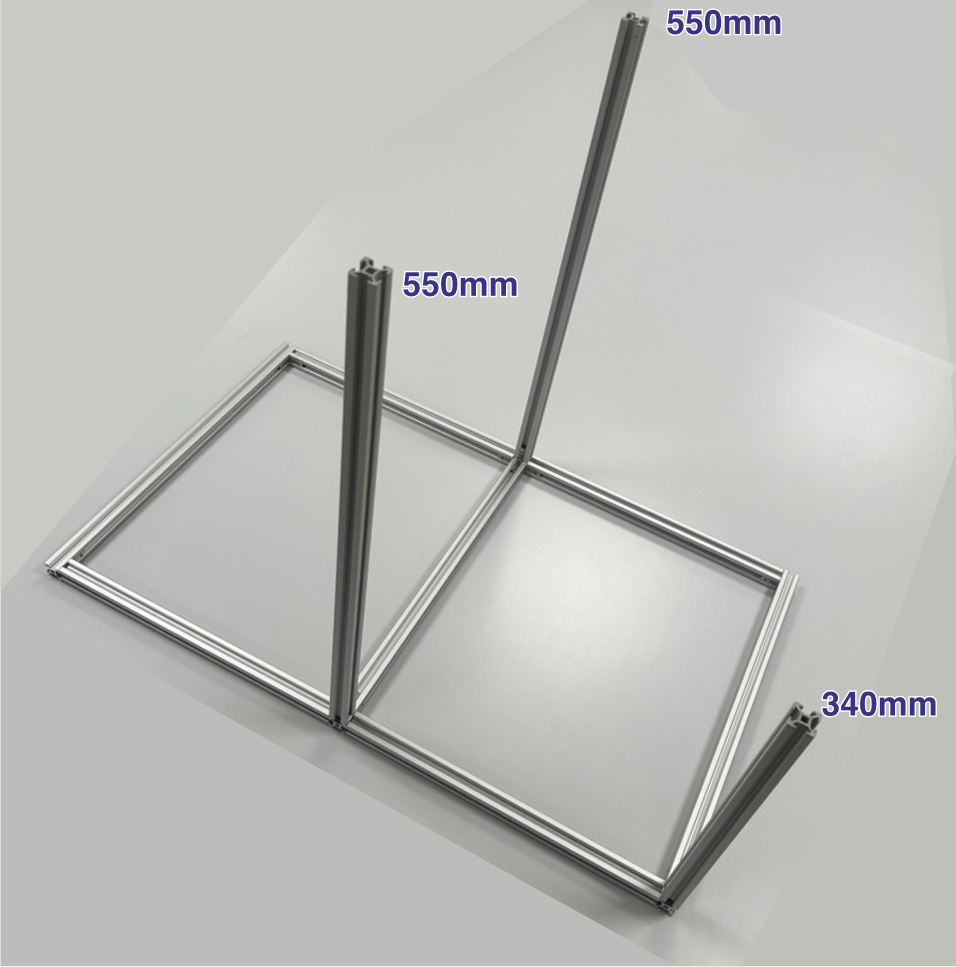
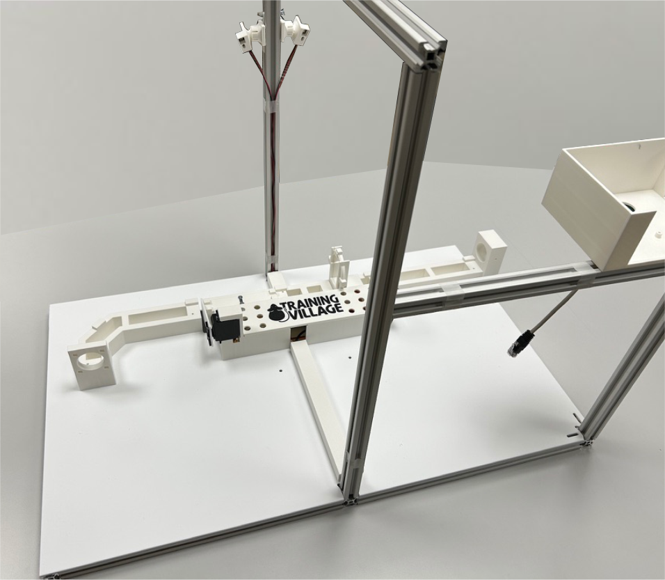
Frame Construction
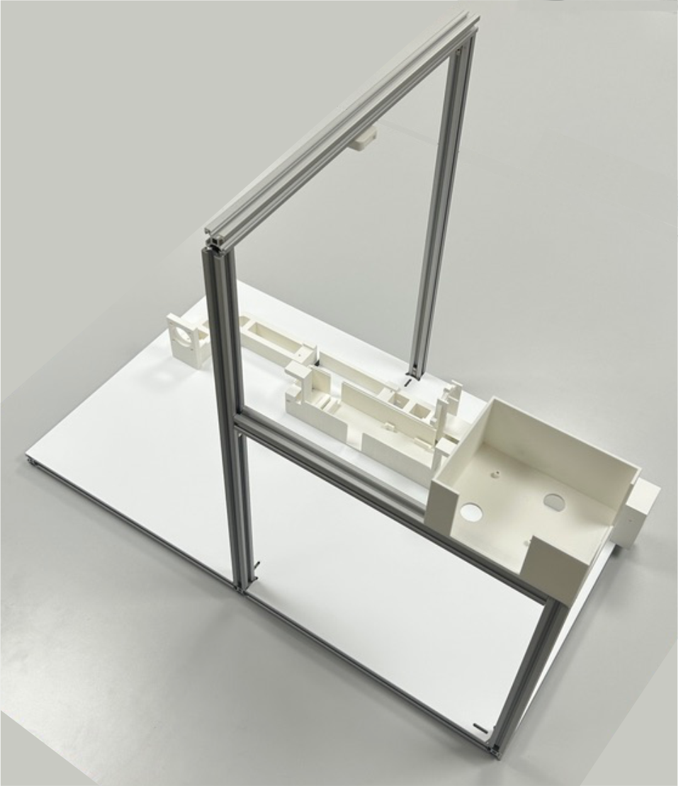
Components: Parts required for the standard 2-homecage version (without Eco-HAB). The frame is built using 20×20 V-slot aluminum profiles.
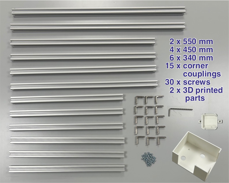
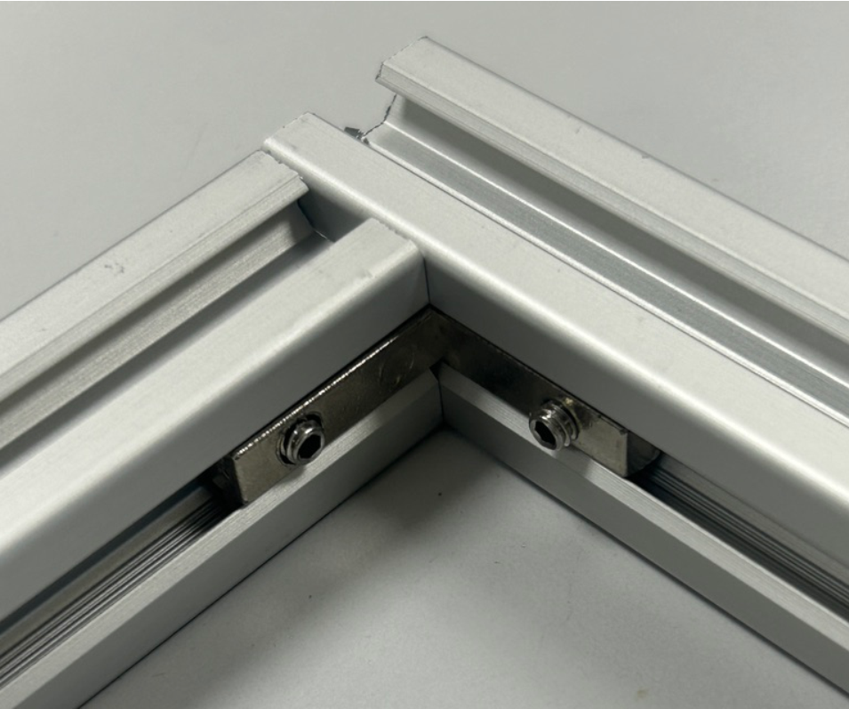
Connections: Pieces are connected using corner couplings and set screws.
Base: Build the base first.
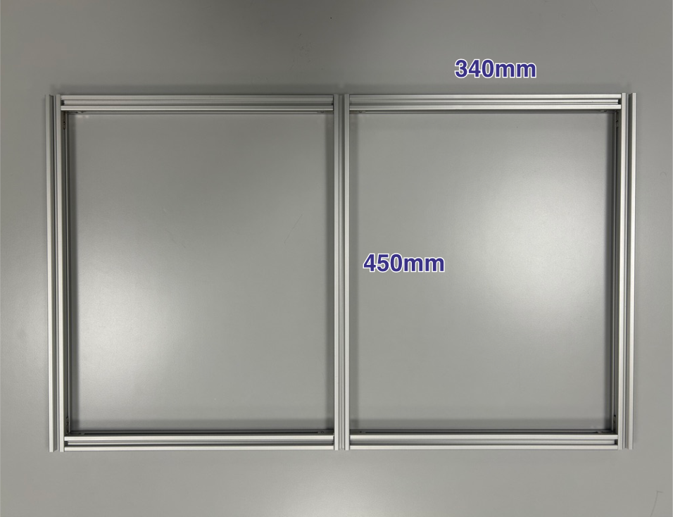
Vertical Pieces: Add the vertical pieces.
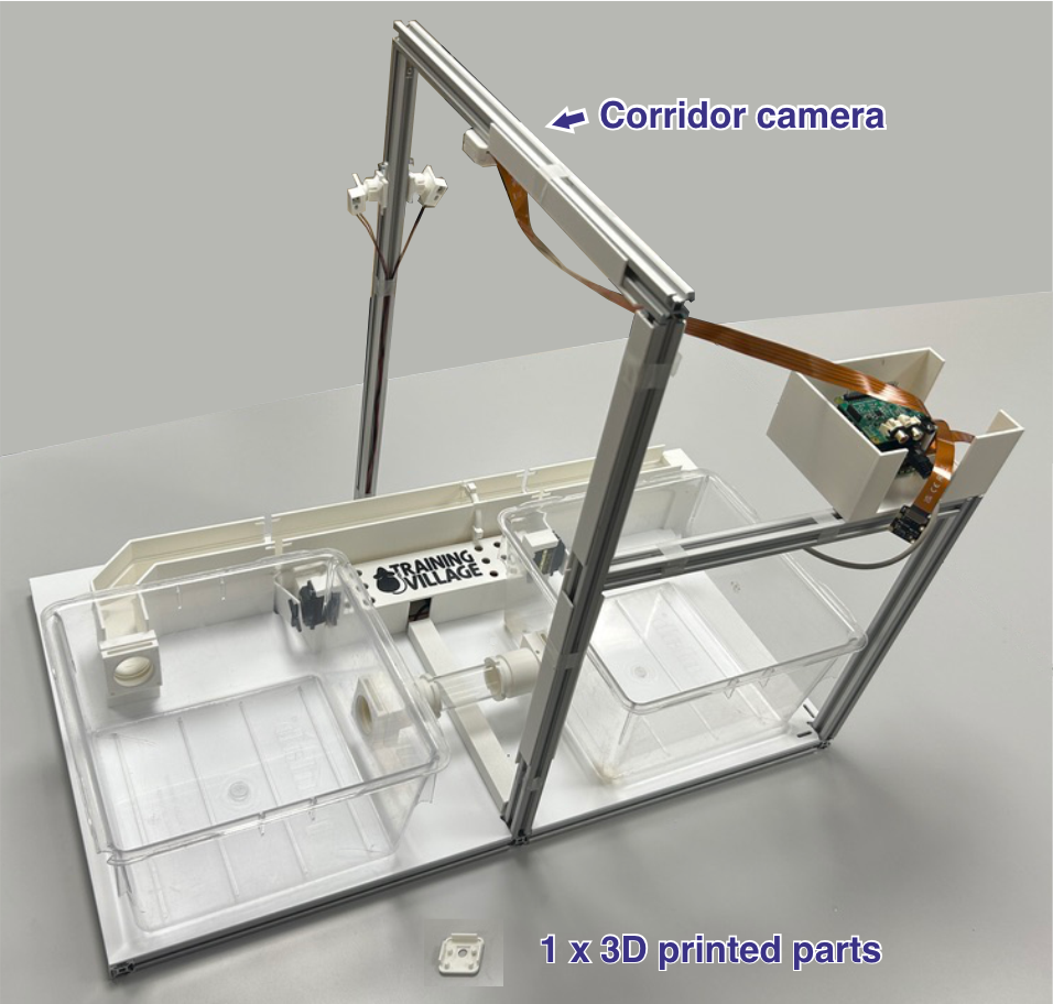
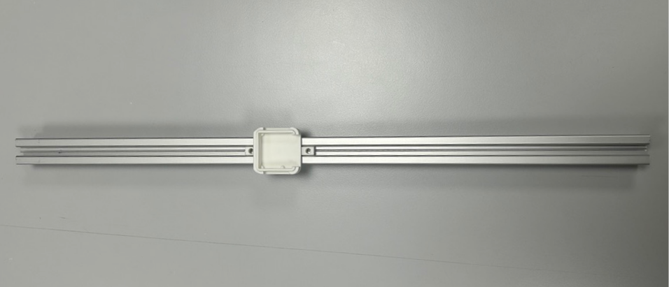
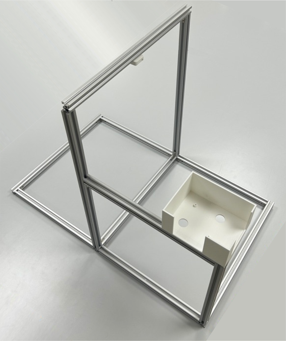
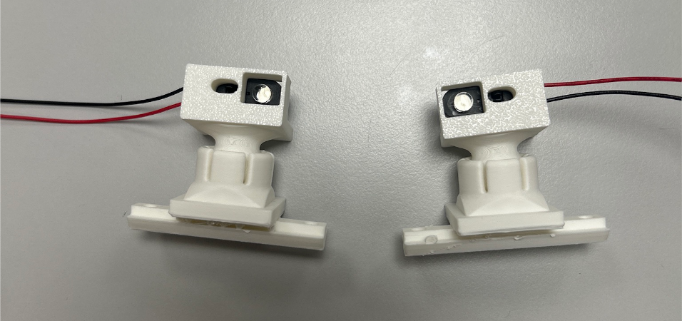
Camera Mount: Slide the 3D-printed camera mount base onto an aluminum profile.
Enclosure: Place the 3D-printed Raspberry Pi enclosure and complete the aluminum structure.
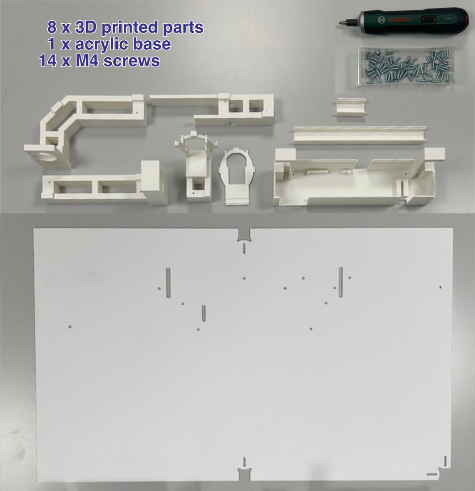
Base Assembly
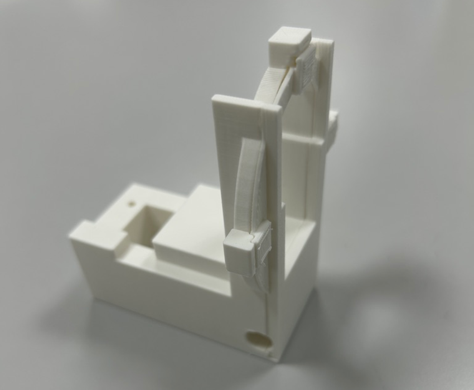
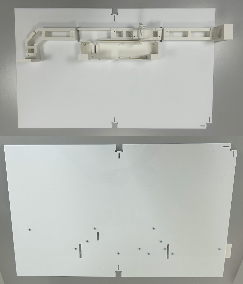
Components: 3D-printed parts and a 3 mm matte white acrylic base. The matte finish is important to avoid reflections.
RFID Antenna Slot: This piece includes a slot designed to hold an external antenna between its two parts. The RFID module used in this build has a built-in antenna, so this slot is not needed in the standard setup. However, if you use a different RFID module — or an Eco-HAB to manage multiple antennas — you can insert an external antenna here.
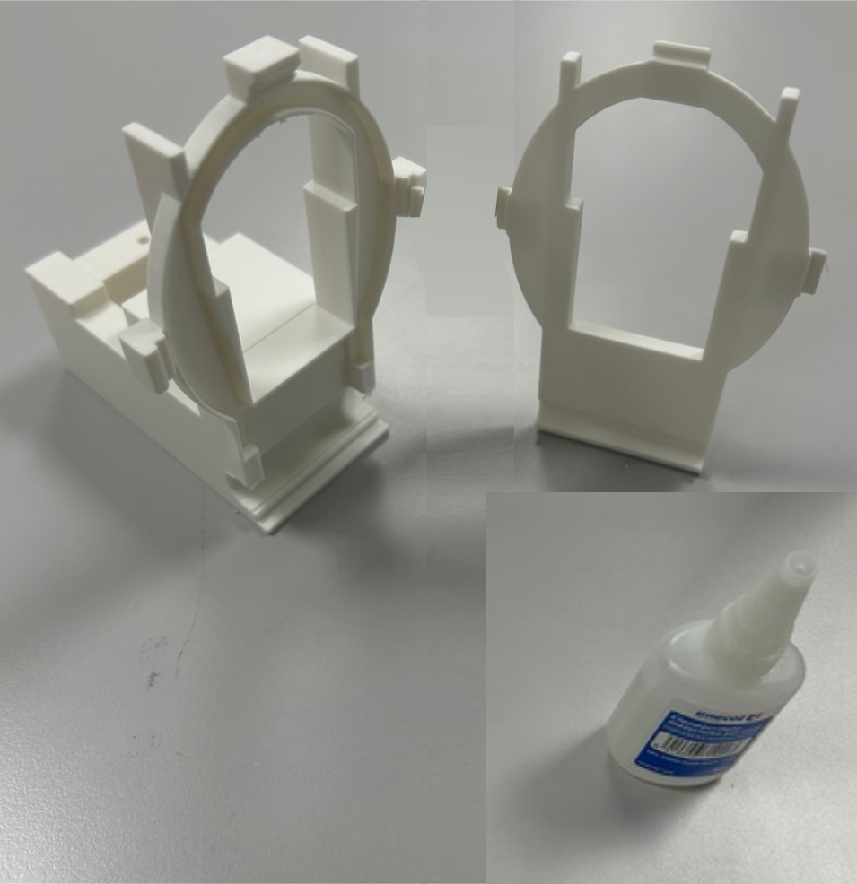
Bonding: Glue the two pieces together.
Parts Mounting: Secure the 3D-printed parts onto the acrylic base using M4 screws, tightening from below.
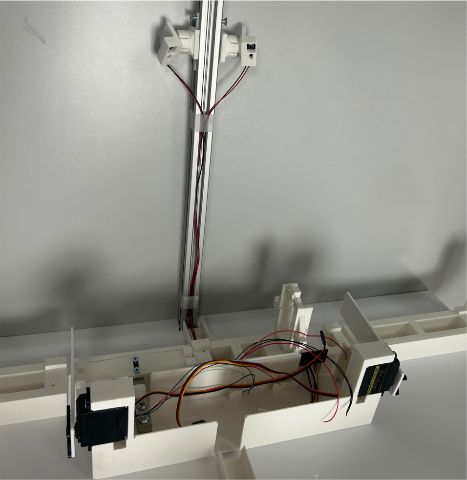
Frame Installation: Place the assembled base onto the aluminum frame structure. You can now slide the camera mount along the profile to align it roughly above the corridor pieces, so the camera records the corridor from directly overhead. Once in position, secure the camera mount with an M4 screw.
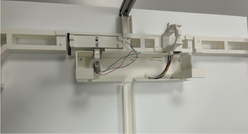
RFID & Load Cell
Components: Scale module (load cell with 3D-printed part) and RFID module.
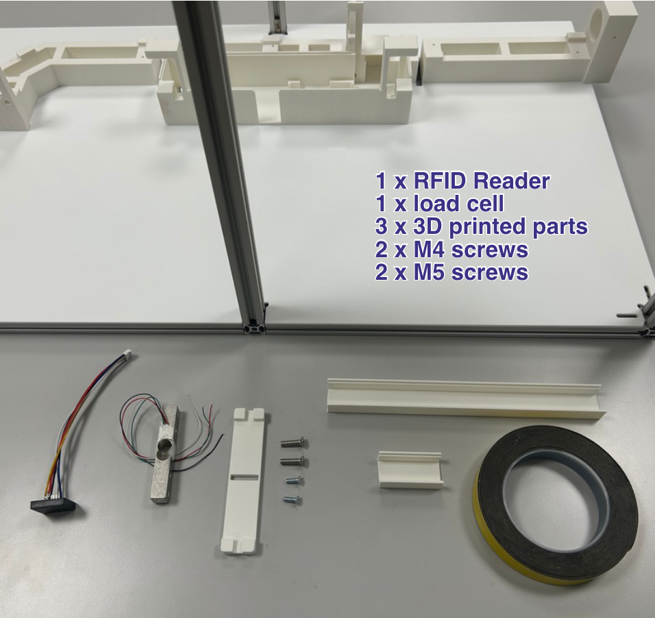
Load Cell Assembly: Attach the 3D-printed part on top of the load cell using M4 screws.
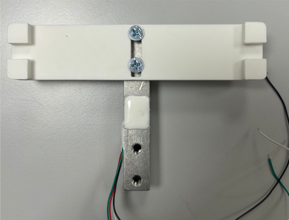
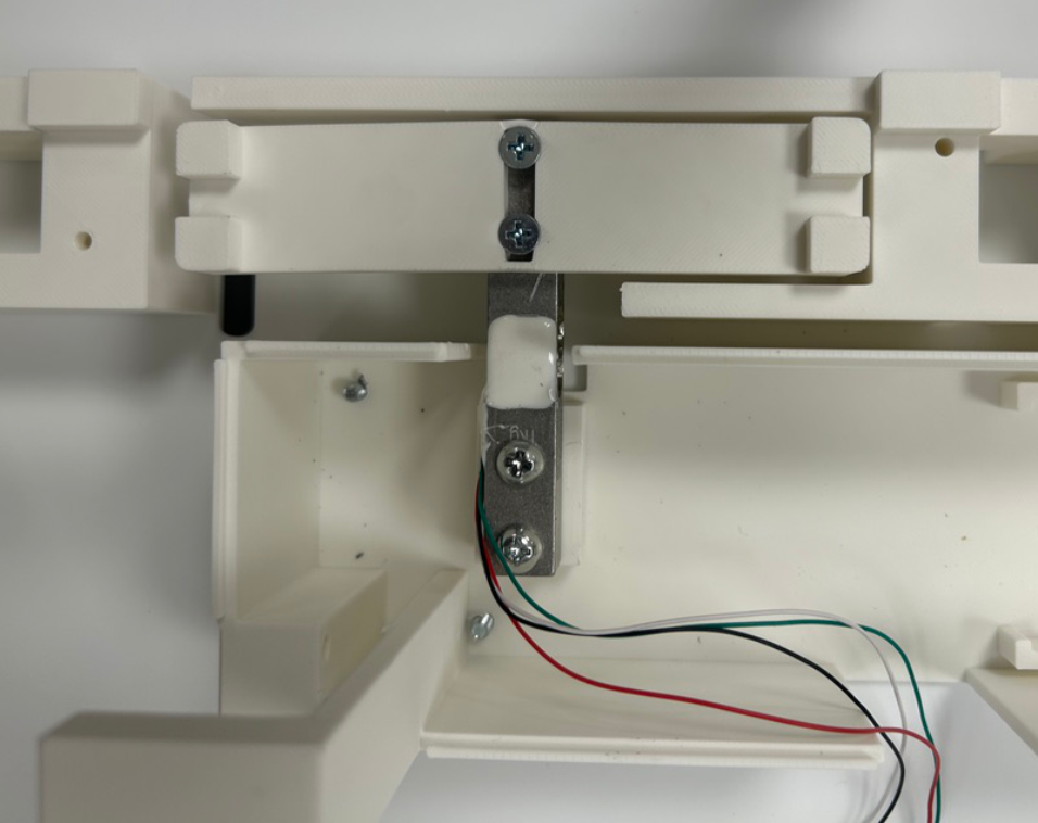
Scale Positioning: Mount the scale onto the base using M5 screws. It must sit straight and centered, without touching any of the surrounding parts.
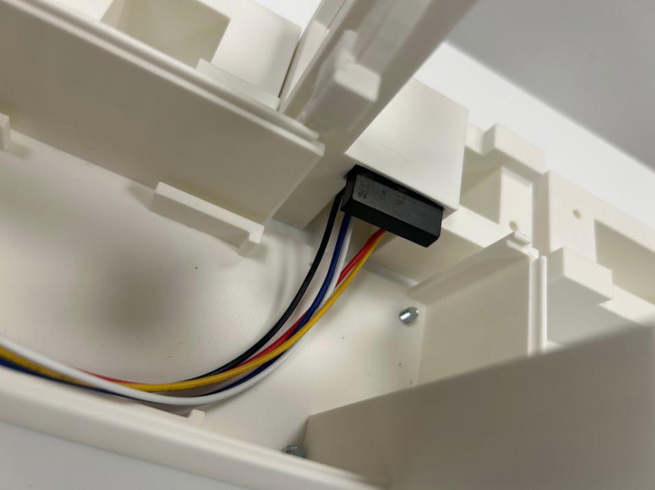
RFID Wiring: This build uses the ID-20LA RFID reader (125 kHz). Solder a 5-pin JST-PH connector following the pin order shown in the diagram. See the specifications for the full pinout.

RFID Installation: Slide the RFID module into its designated slot. Secure it with a small piece of tape to prevent movement.
Cable Management: Attach the two plastic cable guides to the base using double-sided tape, as shown in the image. This completes the assembly with both sensors in place.
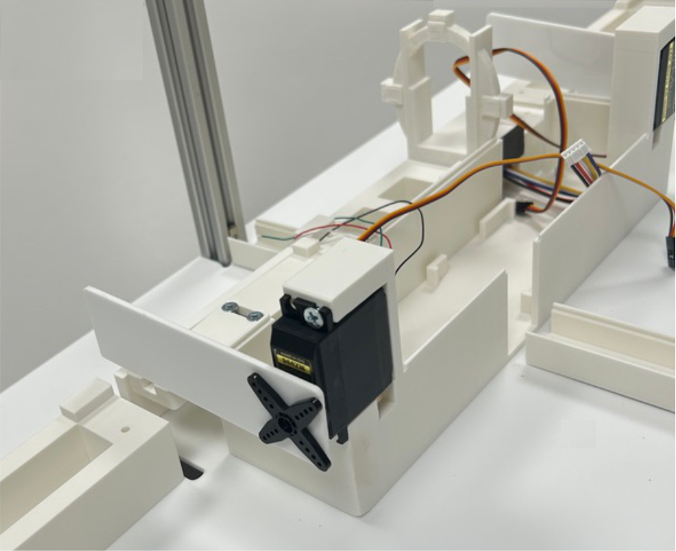
Servo Motors
Components: Servo motors and doors.
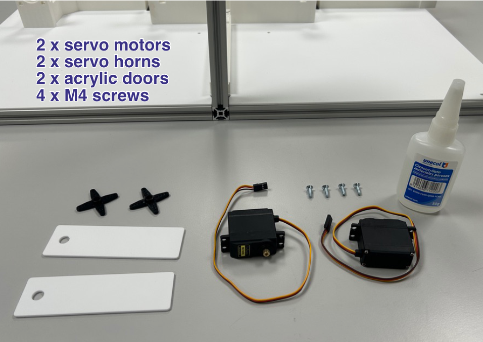
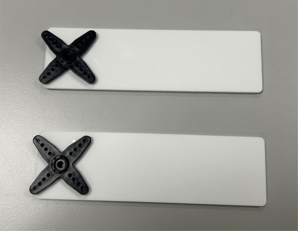
Horn Bonding: Glue the servo horns onto the servos.
Servo Mounting: Secure each servo in position using at least 2 M4 screws.
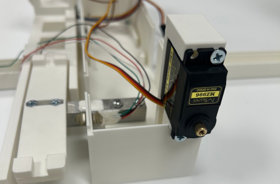
Door Attachment: Connect the doors to the servo motors.
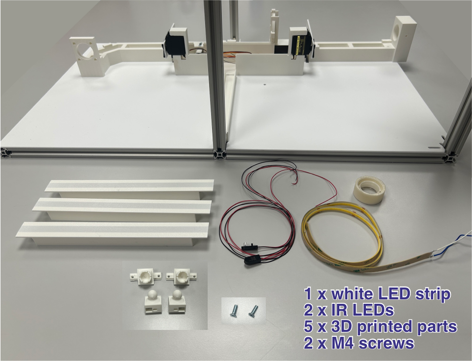
Illumination
Components: White LED strip and IR LEDs. In both cases, the connection requires only two bare wires (ground and power), with no connector.
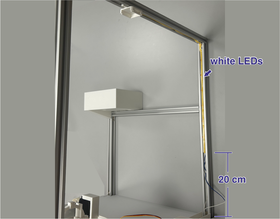
LED Strip Placement: Mount the LED strip on the frame, starting from the vertical profile furthest from the corridor and continuing along the horizontal ceiling profile. Leave approximately 20 cm from the floor to the start of the strip so that the light always stays above the animals’ heads. Along the horizontal profile, extend the strip to approximately the position of the camera mount (which should sit roughly above the corridor pieces).
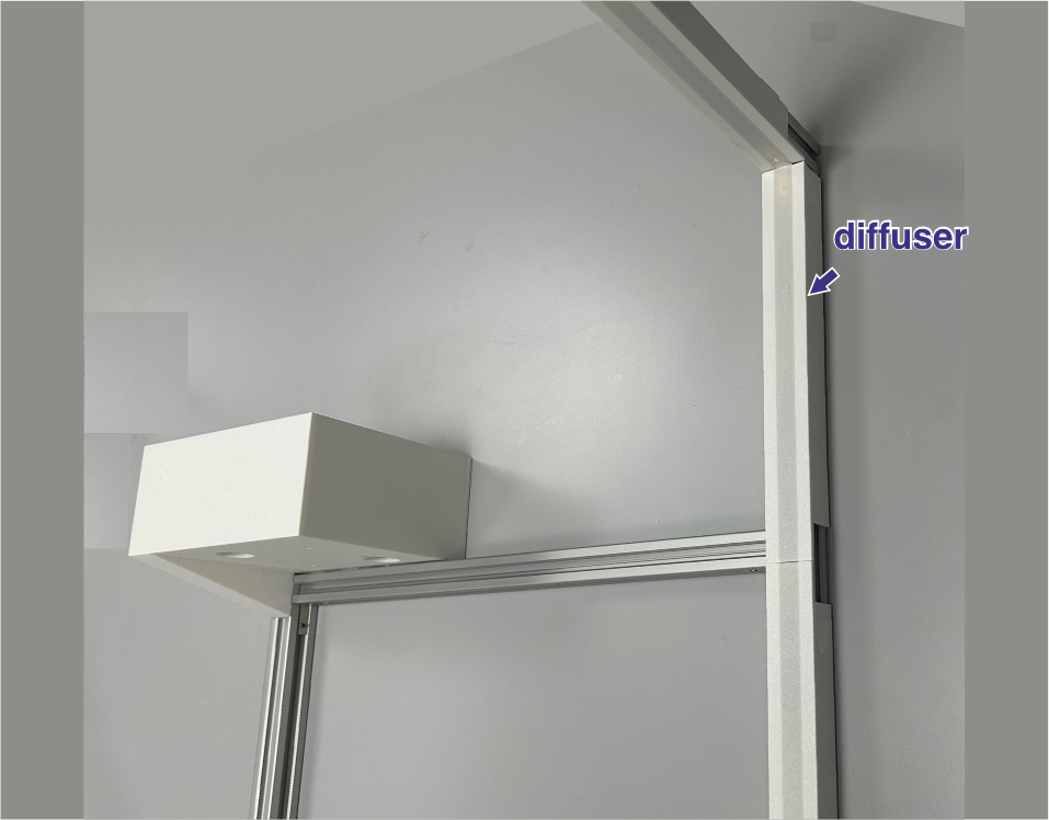
Diffusers: Place the plastic diffusers over the LED strip using adhesive tape.
IR LED Assembly: Insert the IR LEDs into their plastic holders — they snap into place.
IR LED Mounting: Attach the plastic holders with the IR LEDs to the vertical profile opposite the white LED strip — the vertical aluminum profile closest to the corridor. The two 3D-printed mounting parts allow for some adjustment, enabling the IR LEDs to be oriented for optimal illumination of the corridor while minimizing reflections.
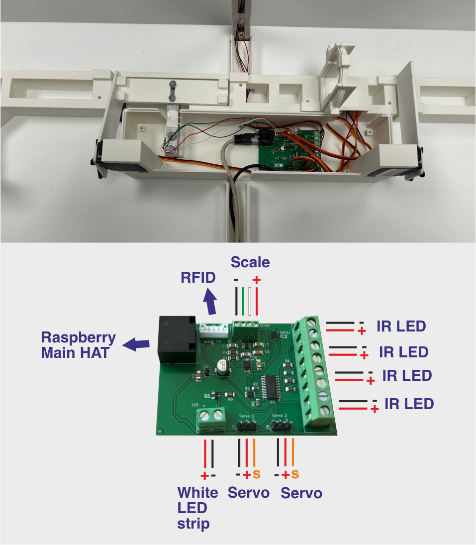
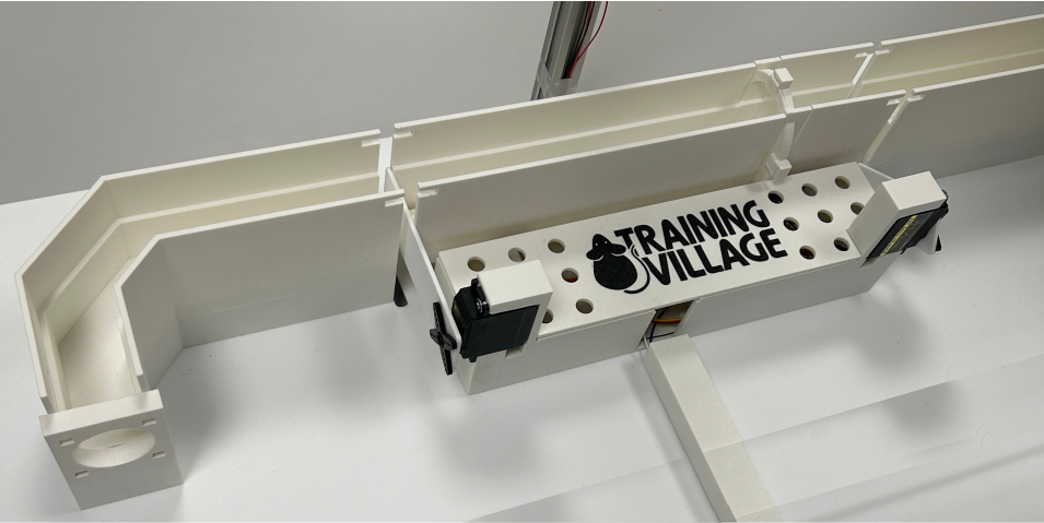
Corridor Board
Components: Corridor Board and an Ethernet cable.
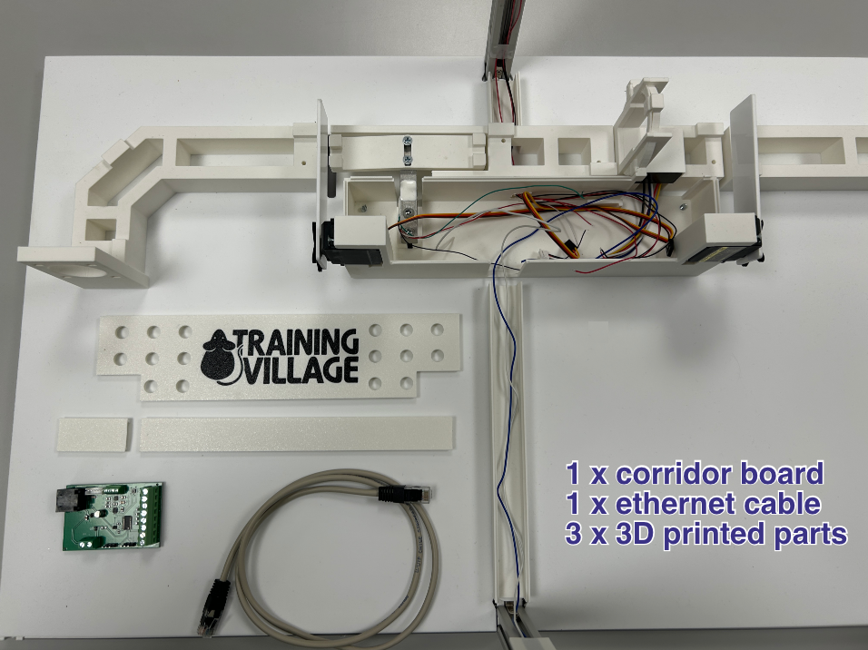
Peripheral Connections: Mount the Corridor Board in its fixed position on the physical corridor frame. Connect its local peripherals: servo motors, RFID reader, weighing scale (load cell), white LED strips, and IR illumination LEDs. Always verify wiring polarities against the board’s silk-screen labels before insertion. Finally, connect an Ethernet cable to link this board to the main Raspberry Pi board.
Enclosure Closure: Once all connections are made, place the cover to close the enclosure housing the Corridor Board, and cover the cable guides as well.
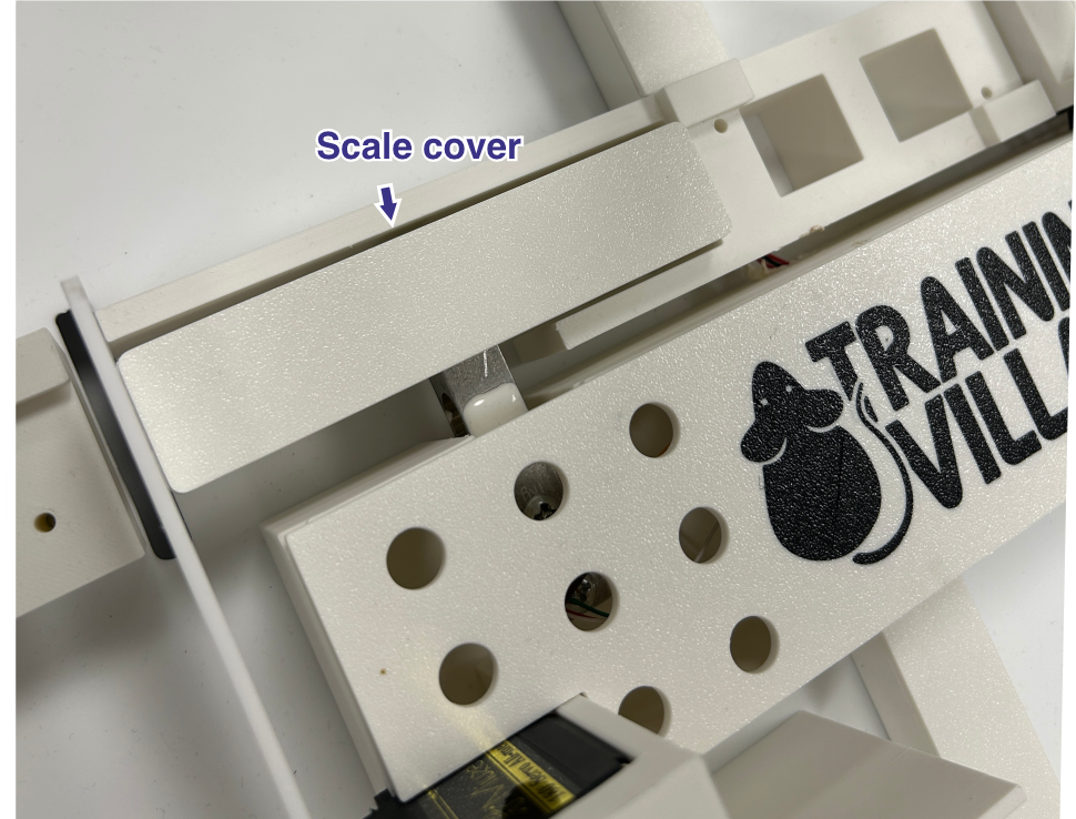
Corridor Parts
Components: The corridor is made up of 5 3D-printed parts.
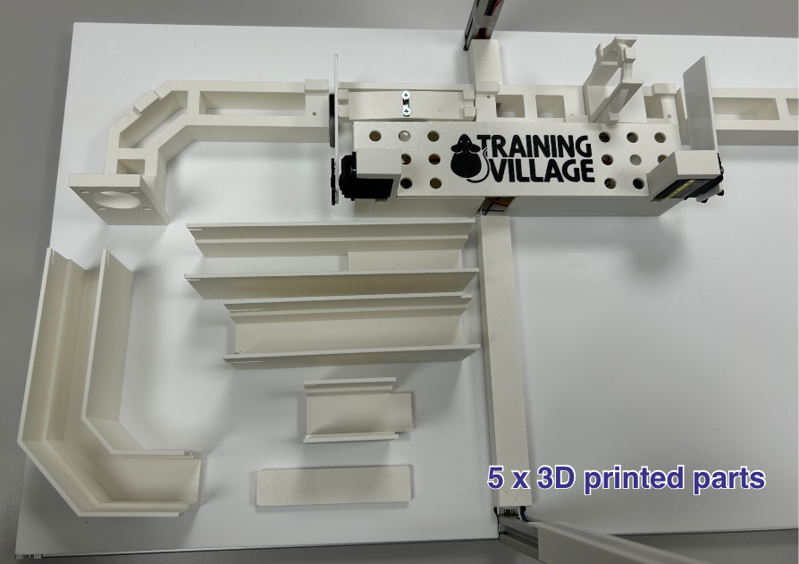
Scale Cover: Start by fitting the piece that covers the scale — it simply clicks onto the base.
Remaining Parts: Place the remaining corridor pieces onto their bases.
Acrylic Cover
Components: A transparent acrylic cover and 4 transparent acrylic stoppers.
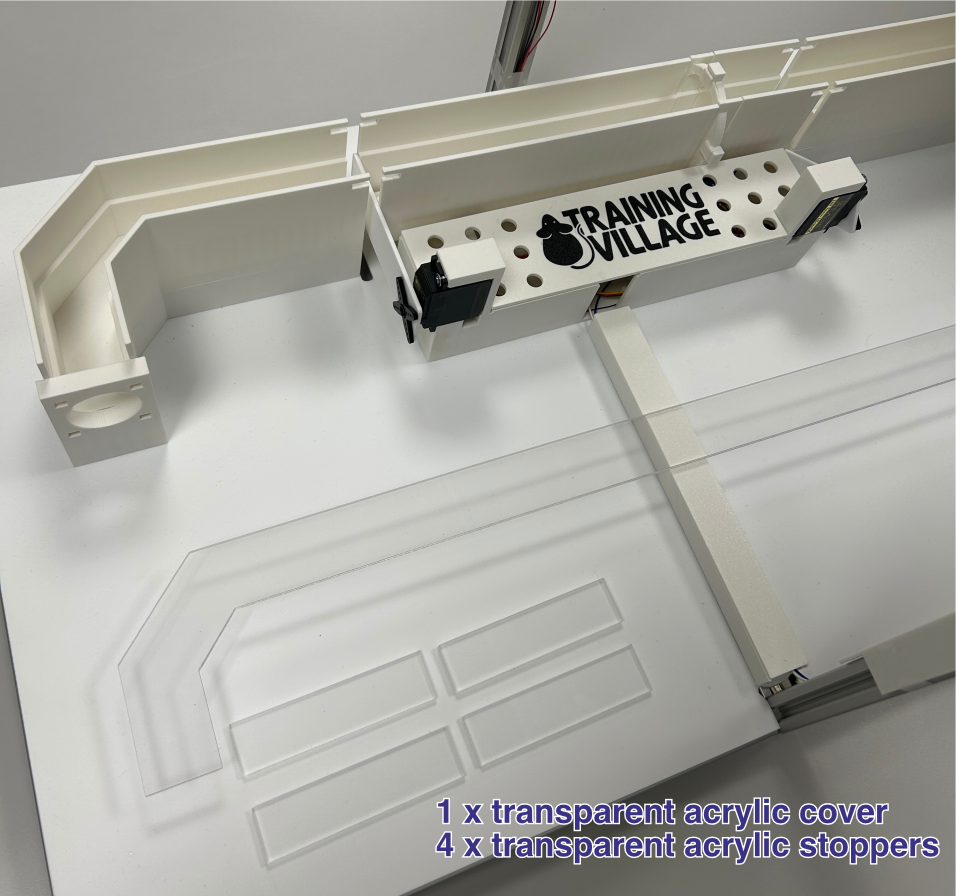
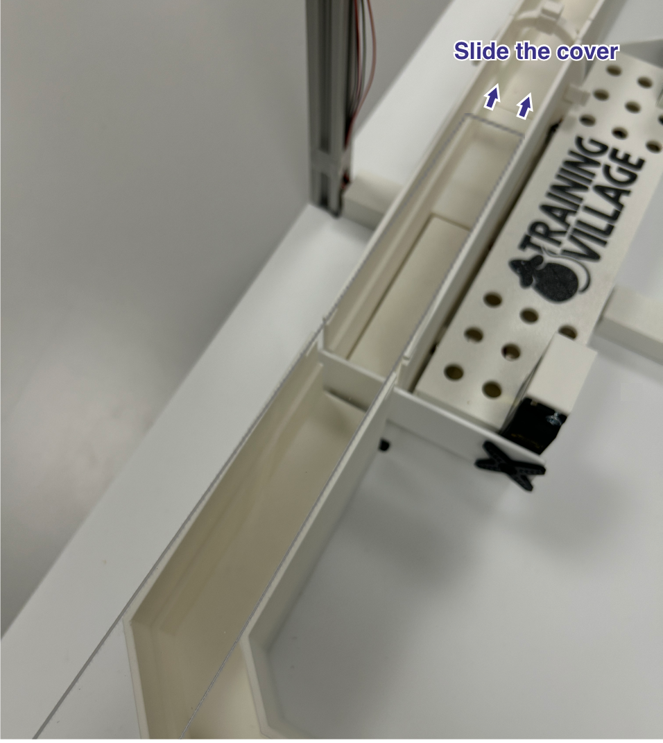
Cover Installation: Slide the cover in from one side until it clicks into position.
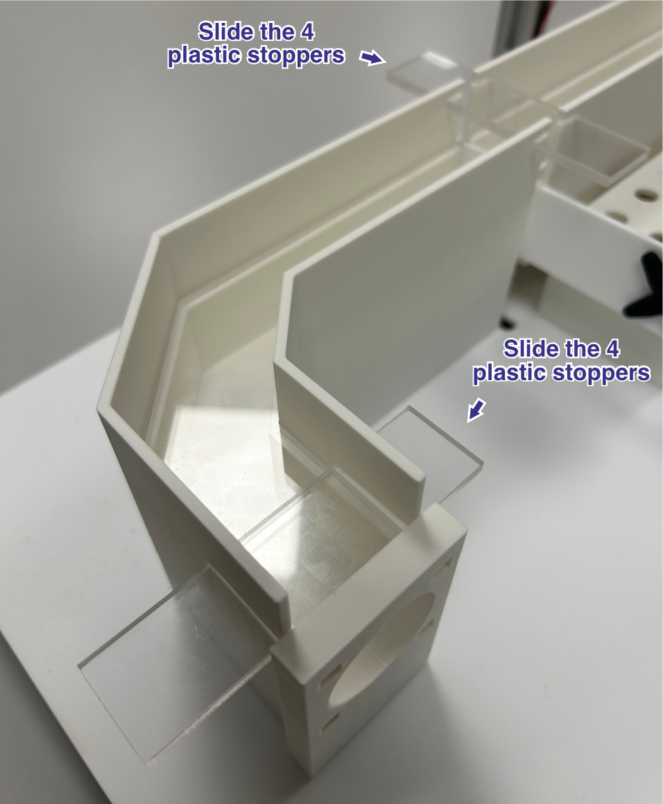
Stoppers: Place all 4 stoppers in their designated positions on top of the cover. This is important — they prevent an animal from pushing the cover up and lifting it off.
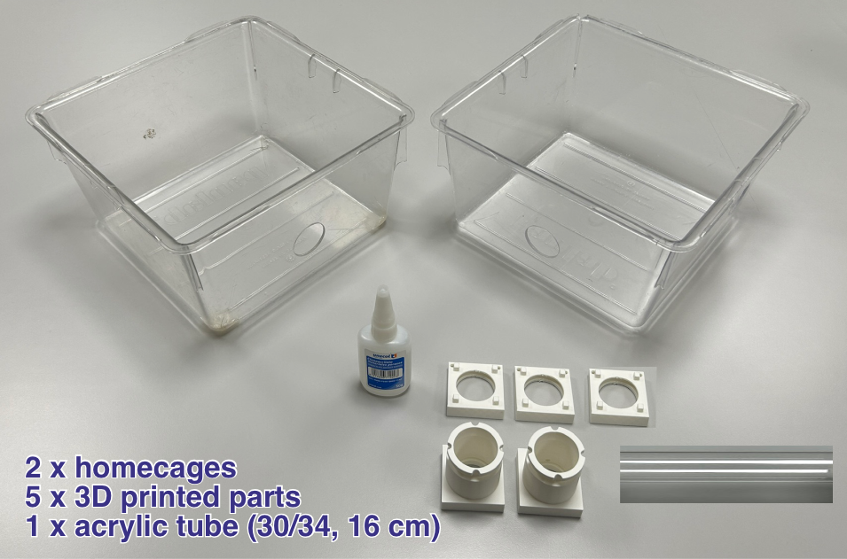
Homecages
Components & Drilling: 2 homecages, an acrylic tube, and 5 3D-printed connectors. Use a hole saw to drill 3 cm diameter circular openings in the positions shown. Both homecages need a centered hole on one side to connect them to each other. The homecage that connects to the corridor needs an additional hole on another side, offset slightly so that the assembly sits correctly on the base when connected.
Connector Bonding: Glue the 3D-printed connectors onto the homecages.
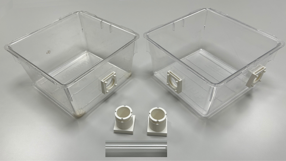
Tube Assembly: Attach the pieces that support the acrylic tube to the homecage connectors, then insert the tube between them.
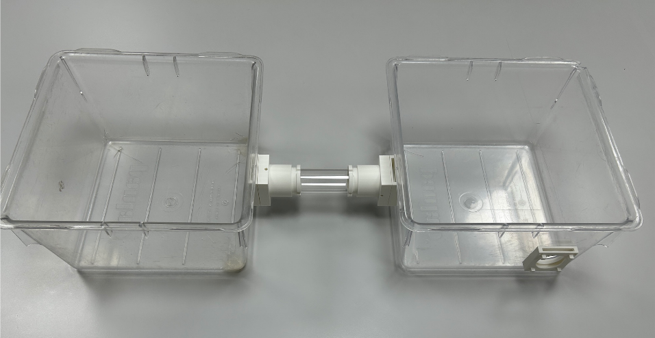
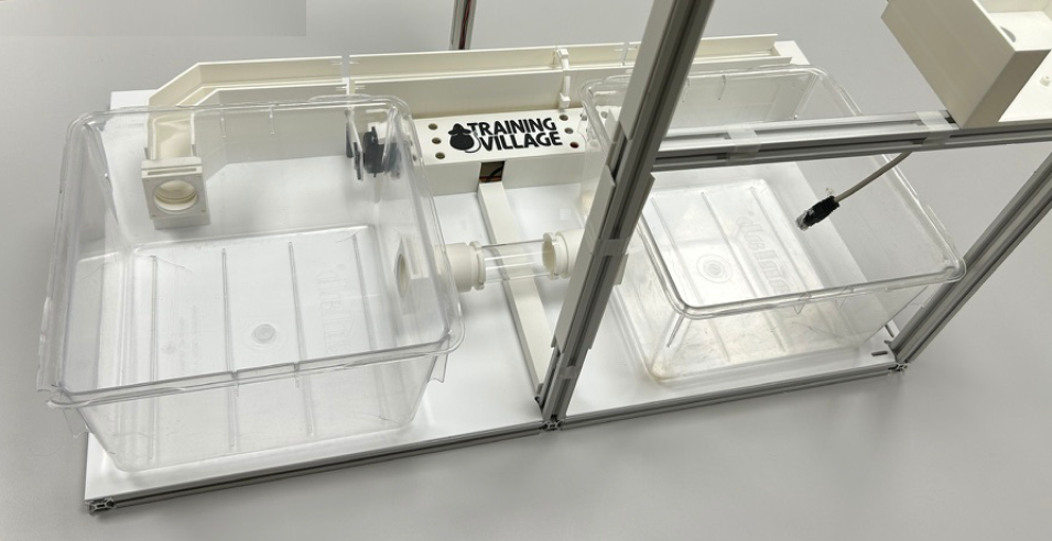
Final Placement: Place the homecages onto the base and connect them to the corridor.
Raspberry Pi Assembly
CRITICAL POWER & WIRING WARNING
Never hot-plug peripherals: ensure the main power supply is completely disconnected before plugging or unplugging any HAT, board, servo, or sensor.
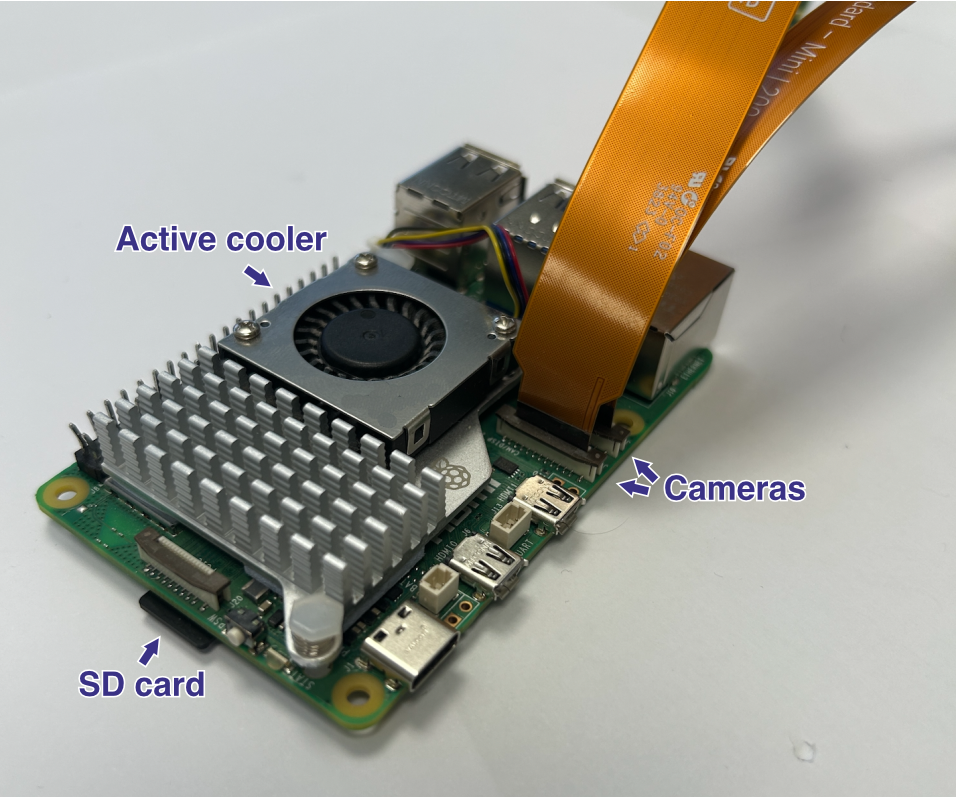
Storage: Insert the pre-loaded microSD card into the Raspberry Pi 5 slot.
Cooling: Securely mount the official Active Cooler onto the processor.
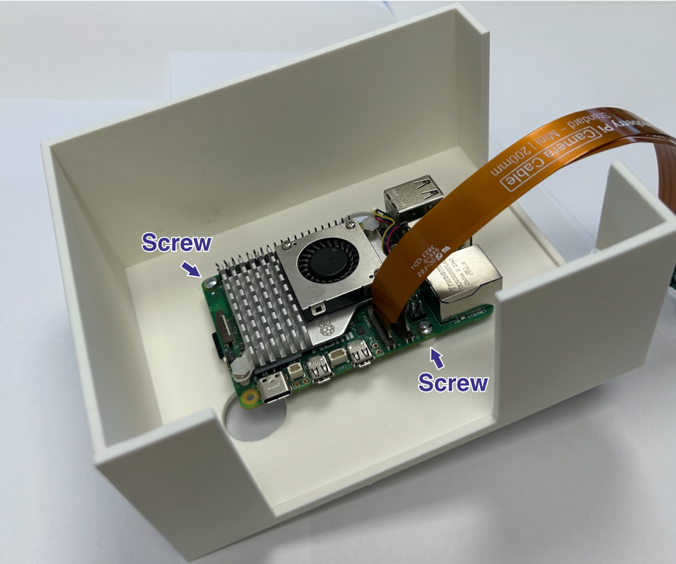
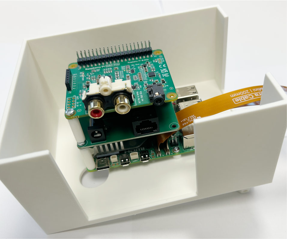
Camera Integration: Connect the two camera ribbon cables to the Pi. Keep cables as short as possible. The corridor camera uses a standard 50 cm ribbon cable; use an extension with a dedicated FFC adapter if needed for the box camera. See the official camera installation guide.
Enclosure Mounting: Place the Raspberry Pi into its dedicated 3D-printed enclosure (Raspberry Box) and secure it with screws.
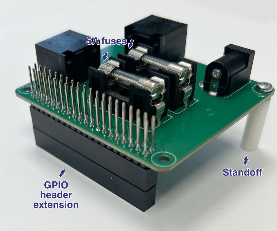
Main HAT Preparation: Insert two 5A fuses into their designated slots on the Main HAT. Install a GPIO header extension/spacer alongside plastic standoffs to ensure proper vertical clearance and prevent short circuits.
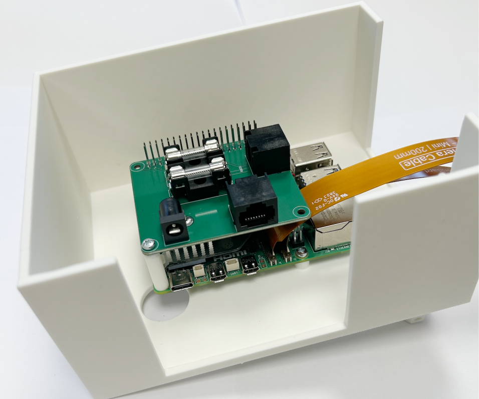
Main HAT Mounting: Align and carefully press the Main HAT down onto the Raspberry Pi’s 40-pin GPIO header.
Audio HAT Preparation: Install another GPIO header extension/spacer and plastic standoffs onto the Audio HAT to stack it safely above the previous layer.
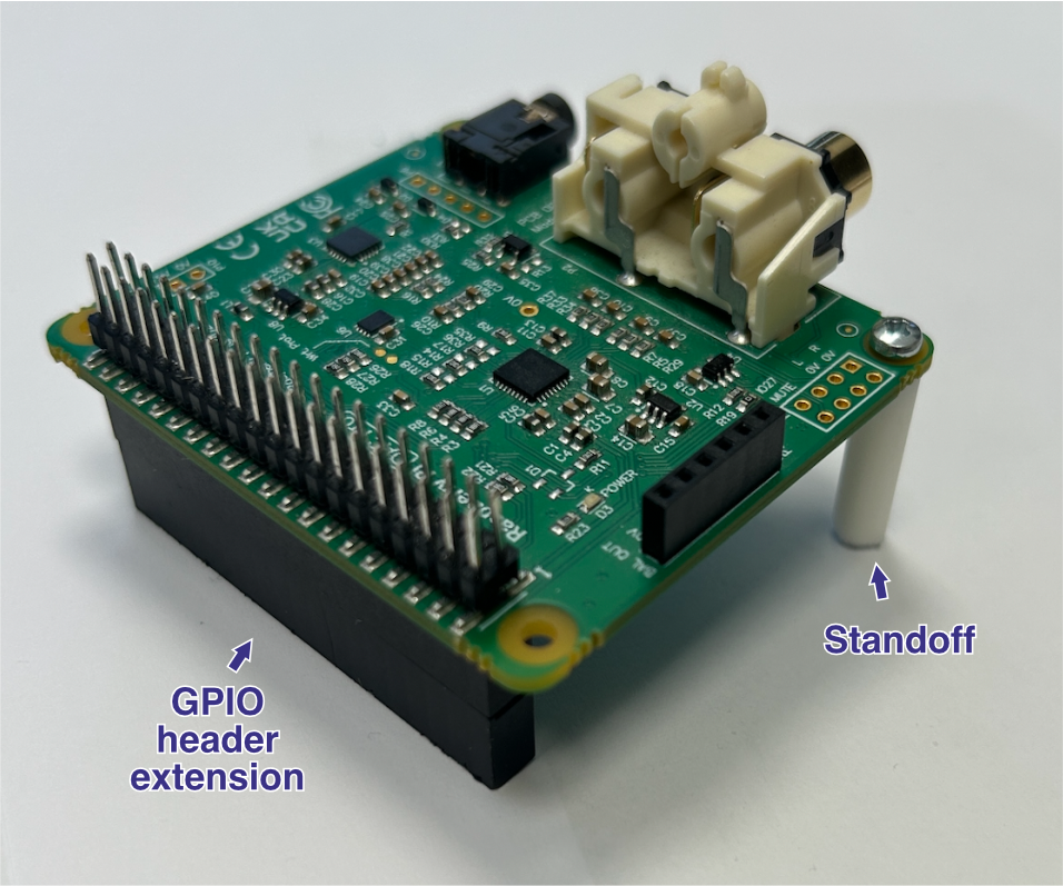
Audio HAT Mounting: Press the Audio HAT firmly on top of the Main HAT, completing the primary hardware stack.
Corridor Camera
Camera Mounting: Place the corridor camera onto its mount above the corridor and secure it with the 3D-printed plastic cover.