
 village
GPIO
A GPIO (General Purpose Input/Output) pin is a digital pin on the Raspberry Pi that can either read an external signal (input) or drive one (output). Unlike the specialized connectors on the corridor and box boards (servos, lighting, RFID…), a GPIO pin has no fixed purpose — it is a generic way to wire the system to whatever external hardware you need: an optogenetics TTL line, a lickometer, a mechanical switch, a sync pulse to another device, and so on.
Setup
Voltage
The Raspberry Pi’s GPIO pins operate at 3.3 V logic and are not 5 V tolerant — connecting a 5 V signal directly to an input pin can damage the Pi. If your external hardware works at 5 V or higher, use a level shifter, a relay, or an optocoupler between it and the Pi rather than wiring it directly.
Input: reads HIGH (~3.3 V) or LOW (~0 V). By default the pin is configured with an internal pull-down, so an unconnected input reads LOW (see Pull-down or pull-up).
Output: drives HIGH (3.3 V) or LOW (0 V). Like all Raspberry Pi GPIO pins, it can only source a small current (a few mA) — enough to trigger a relay, optocoupler, or logic-level input on another device, but not enough to drive a motor, solenoid, or high-power LED directly.
Where to connect
You can wire directly to the Raspberry Pi’s 40-pin GPIO header. In the
standard assembly, though, the Main HAT and Audio HAT are stacked on top of
the Pi using pass-through GPIO header extensions (see
Raspberry Pi Assembly), so every pin — including
GPIO_IN/GPIO_OUT — is also exposed on the header on top of the HAT stack,
which is usually easier to reach once the Pi is mounted in its enclosure.
Note
The pins are given in BCM numbering (the Broadcom channel number), not the physical pin position on the 40-pin header — see the pinout below.
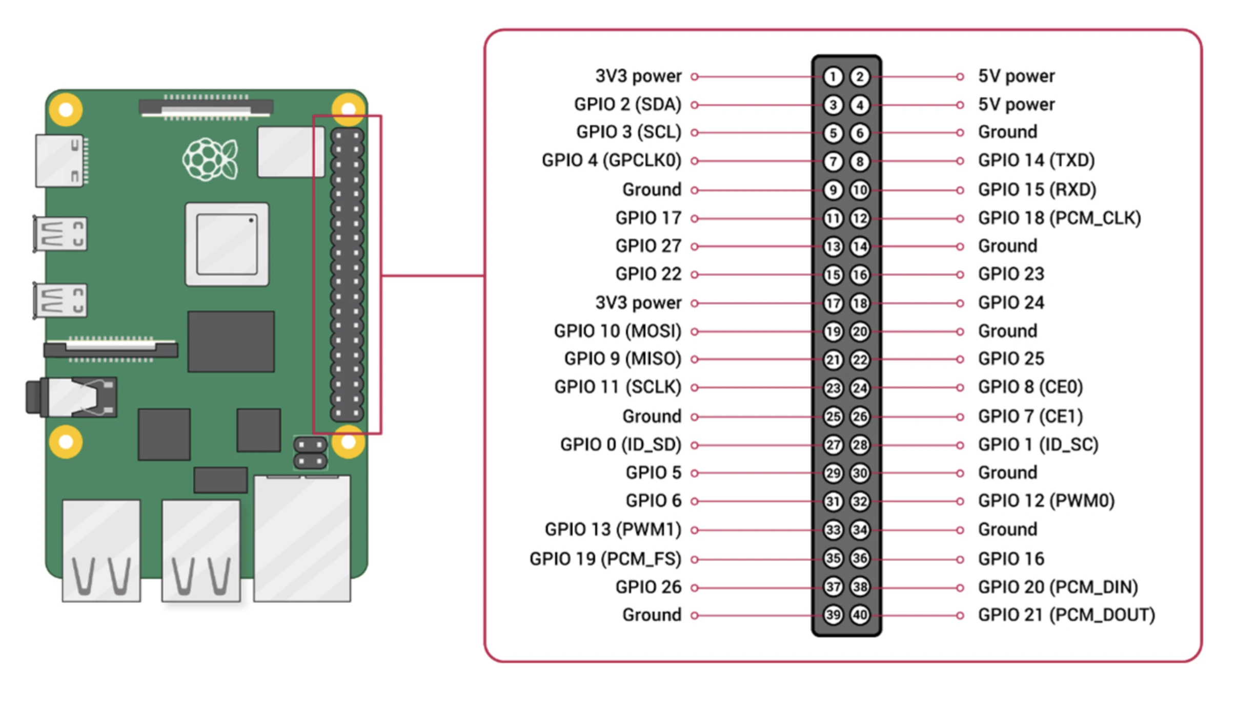
Pins
GPIO_IN is BCM 26 and GPIO_OUT is BCM 27. They are fixed (they cannot be
changed from SETTINGS), and both are free — neither the Main HAT nor the Audio HAT
uses them.
GPIO_IN (BCM 26) is already wired, at the PCB level, to the Switch
Connector on the Box Board: it lets a mechanical switch drive the pin
directly, going HIGH when the switch is activated and LOW when it is
released, without any extra wiring. See
Satellite Board 2: The Box Board
for the full list of Box Board connectors.
Pull-down or pull-up
GPIO_IN_PULL (SETTINGS → ADVANCED SETTINGS) chooses the internal resistor of
GPIO_IN, and with it what turns the input ON:
|
Nothing connected |
ON when |
Use it for |
|---|---|---|---|
|
LOW, OFF |
the pin receives 3.3 V |
the Switch Connector of the Box Board, a TTL signal |
|
HIGH, OFF |
the pin is connected to ground |
a switch between the pin and ground |
In both cases trigger_on is called when the input turns ON and trigger_off when
it turns OFF. A change is applied from the next task.
Note
If your hardware already has its own resistor on that line, choose the setting
that matches it: an internal pull-up fighting an external pull-down (or the other
way around) leaves the pin at an intermediate level. To check what is wired,
run python3 village/scripts/check_gpio_in.py on the Raspberry Pi with Village
closed: it prints every change of the pin, with the resistor of GPIO_IN_PULL
(or another one, with --pull up, --pull down or --pull none).
Using It in Tasks
The output pin (GPIO_OUT) is available at all times via gpio.set_on() and
gpio.set_off(), regardless of the input pin’s state — call them from
anywhere: a task, a trigger, a direct function, and so on.
from village.devices.gpio import gpio

gpio.set_on()   # drives GPIO_OUT HIGH
gpio.set_off()  # drives GPIO_OUT LOW
Reacting to the Input Pin
The system watches an input pin (GPIO_IN) while a task is running. Every time
it goes from OFF to ON the trigger_on method of GpioTriggerBase is called;
every time it goes from ON back to OFF, trigger_off is called. ON is HIGH by
default, or LOW with GPIO_IN_PULL set to UP (see
Pull-down or pull-up). By
default both do nothing. You can override them to react to an external signal
(an optogenetics TTL, a lickometer, another box, …).
Creating a custom GpioTrigger
Create a file inside your project’s code directory (e.g. gpio_trigger.py) and define
a class (e.g. GpioTrigger) that inherits from GpioTriggerBase. The file and class names are
up to you: the system detects the class by what it inherits from, and uses it
instead of the default base class. Only one such class is used per project.
from village.custom_classes.gpio_trigger_base import GpioTriggerBase


class GpioTrigger(GpioTriggerBase):

    def __init__(self) -> None:
        super().__init__()

    def trigger_on(self) -> None:
        """Called when the input pin goes from OFF to ON.

        Available via self.task:
        - self.task.cam_box      — box camera (write_text, areas, position, …)
        - self.task.bpod         — Bpod controller (send_softcode_to_bpod, …)
        - self.task.gpio         — set_on()/set_off() for the output pin
        - any attribute defined in the task class
        """
        self.task.cam_box.write_text("GPIO: ON")
        self.task.bpod.send_softcode_to_bpod(1)

    def trigger_off(self) -> None:
        """Called when the input pin goes from ON to OFF."""
        self.task.cam_box.write_text("GPIO: OFF")
Note
trigger_on/trigger_off run in the GPIO reader thread, not in the task
thread. Keep them fast and avoid blocking calls. They are only called once the
start of the task has finished, so they can read any attribute start creates,
and never in calibrations. An error raised inside them sends an “Error in the GPIO
trigger” alarm (at most one per hour, with the traceback in the events log), and the
pin keeps being watched.
A complete example, which records the pin in the trial data of any task: gpio_trigger.py.